![]()
![]()


Choosing between a CMM and a 3D scanner is not simply a tradeoff between accuracy and speed. It depends on the purpose of the inspection. Quality teams may need to verify critical dimensions, capture full surface geometry, document deformation, or recreate CAD data from an existing part. This guide compares both technologies in practical terms so QC engineers and designers can decide when to use a CMM, when to use a 3D scanner, and when a hybrid measurement system may be the better choice.
CMMs and 3D scanners are both used in industrial metrology, but they collect data in very different ways. A coordinate measuring machine uses a contact probe to capture selected points on a part, then uses those points to verify dimensions, geometric features, and tolerances. This makes a CMM well suited for drawing-based inspection, including GD&T requirements for holes, planes, cylinders, and critical datums.
A 3D scanner captures the visible surface of a part as a dense point cloud, which can then be converted into a mesh or 3D model. Rather than measuring a limited set of defined features, it records surface geometry at high density across a broader area. This makes 3D scanning useful for reverse engineering, free-form surfaces, deformation checks, and understanding the overall shape of a part.
The key question is not which technology is better. It is what you need to measure: precise features and tolerances, overall surface form, or both. For many QC teams, making that distinction helps avoid buying a fast scanner for tolerance work that requires a CMM, or using a precise CMM for applications that require broader shape data.
When tight dimensional accuracy is the priority, CMMs have a clear advantage. A contact CMM measures defined points directly, using calibrated axes and probes to verify specific dimensions and geometric relationships. Depending on the machine, environment, and setup, CMM measurement is commonly discussed in the micron range, and high-end systems can support sub-micron to several-micron level inspection.
That level of confidence matters when the tolerance window is very small. Aerospace components, medical devices, precision-machined parts, and safety-critical components often require inspection at or below ±0.01 mm. For hole diameter, true position, flatness, perpendicularity, and other GD&T checks, the controlled point measurement of a CMM is still difficult to replace.
Industrial structured-light and laser scanners can be highly capable, but typical practical accuracy is often around ±25 to ±50 µm. Results can also be affected by reflective, black, transparent, or hard-to-access surfaces. In a direct accuracy comparison, CMMs usually have the edge. However, accuracy only matters in context. The best tool depends on the inspection decision you need to support.
3D scanners stand out when speed and coverage are the priority. A scanner can collect hundreds of thousands or even millions of points in a short time, making it practical to capture complex surfaces, organic shapes, molded parts, castings, welded assemblies, and tooling surfaces that would be slow to measure point by point.
This is especially valuable when the goal is to understand the whole part, not just a few defined features. Reverse engineering, die and mold wear checks, weld distortion analysis, CAD-to-scan comparison, and free-form profile inspection all benefit from dense surface data. A color deviation map can quickly show where a part has shifted, warped, worn, or deviated from nominal geometry.
A CMM can measure selected points on the same surface, but covering the entire area would require many programmed touches and significantly more time. That said, speed does not make scanning the best choice for every inspection task. For pass/fail decisions on tight GD&T tolerances, such as a precision bore diameter, CMM probing remains the safer method.
A practical way to choose between a CMM and a 3D scanner is to start with the inspection goal. If the task is First Article Inspection, where dimensions must be verified against a drawing and documented in a formal report, a CMM is usually the stronger choice. For In-Process Inspection, a CMM is also recommended, especially a portable model that can be used near the machine or directly on the shop floor.
If the task is reverse engineering, a 3D scanner is typically more efficient because it captures the full surface data needed to rebuild CAD geometry. Tool and die wear inspection also favors scanning, since changes across a broad surface are often more important than a single point dimension. Surface profile and free-form inspection may use scanning alone or a combined workflow, depending on the required tolerance.
For GD&T compliance in aerospace or medical manufacturing, a CMM is essential. But if one team needs both dimensional inspection and full-shape capture, the next question is whether one system can support both workflows.
For teams that need both point-based accuracy and full-surface data, a CMM with scanning capability can help bridge the gap. One option is to add a scanning probe or sensor to a fixed CMM. This expands the system’s measurement capabilities, but it is still tied to the inspection room and may not be convenient for large parts, fixtures, or shop-floor checks.
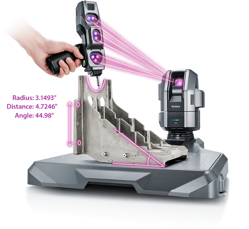
Another option is a portable CMM with integrated laser scanning. This gives engineers the ability to probe critical dimensions when tolerances are tight, then scan surfaces when shape, deformation, wear, or reverse engineering data is needed.
The KEYENCE WM Series is an example of this hybrid approach. It supports contact-probe CMM measurement and handheld 3D laser scanning, allowing users to combine dimensional checks and dense scan data in a single workflow. If you need both accuracy and coverage, review a laser scanning CMM, compare available CMM options, or explore a portable CMM designed for on-site measurement.
Source: KEYENCE Website(https://www.keyence.com/products/measure-sys/cmm/xm/index_pr.jsp)
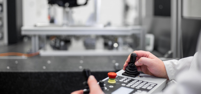
This CMM has a caliper-like feel, enabling even beginners to perform high-precision measurements. It can be carried without the need for temperature control, allowing for immediate measurements at any desired location and time. As it doesn't require a large installation space, it's a CMM with a low entry barrier.
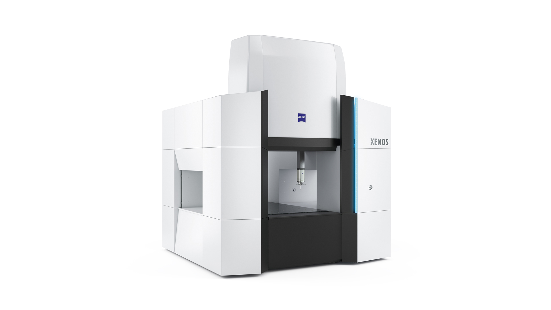
Source: Carl Zeiss Website(https://www.zeiss.com/metrology/products/systems/cmm.html)
Utilizing linear drive on all axes, this CMM boasts high precision with a maximum permissible length measurement error of 0.3+L/1000μm, repeatability of ±0.2μm, and resolution of 0.001μm. The reduced occurrence of errors allows for a decrease in the need for remeasurement.
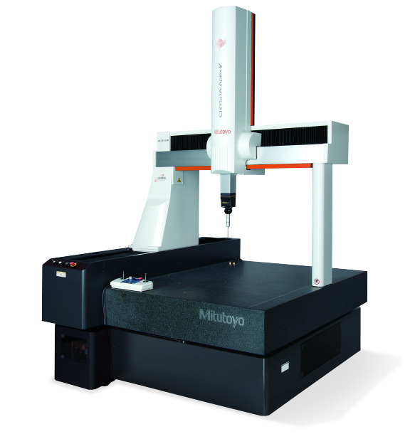
Source: Mitutoyo Website(https://www.mitutoyo.com/products/coordinate-measuring-machines/)
A CNC CMM that was first developed in 1976.
It features applications that respond to the demand for "Smart Factories" by allowing monitoring of operational status and maintenance management of the machine through the network.
Reasons for Selection