![]()
![]()


In precision manufacturing, the functional performance of rotating components depends heavily on how accurately those components rotate around their intended axis. Even small deviations can lead to vibration, noise, uneven wear, or reduced service life. To control such rotational accuracy, runout tolerance is widely used in geometric dimensioning and tolerancing (GD&T).
Runout tolerance evaluates the variation of a surface as a part rotates relative to a specified datum axis. Because this tolerance directly reflects functional behavior during rotation, it is commonly applied to shafts, bearings, gears, and other cylindrical or rotational features.
With the increasing need for repeatable, traceable, and data-driven inspection, Coordinate Measuring Machines (CMMs) have become an effective tool for evaluating runout tolerance. This article explains the fundamentals of runout tolerance, including circular runout and total runout, and outlines how these tolerances are measured using a CMM in practical inspection environments.
Runout tolerance is a geometric tolerance defined in standards such as ASME Y14.5 and ISO GPS. It controls how much a surface varies when a part is rotated about a datum axis. Unlike size tolerances, runout tolerance does not simply evaluate dimensions; instead, it assesses the relationship between a surface and a functional axis of rotation.
A key characteristic of runout tolerance is that it is always datum-referenced. The evaluation depends on how the part is aligned to the datum axis, which is typically derived from a cylindrical or conical feature that represents the functional rotation axis.
Runout tolerance can be considered a composite control because it reflects the combined influence of form, orientation, and location errors. For this reason, it is especially valuable when functional performance is more important than isolated geometric characteristics.
Circular runout controls surface variation at individual cross-sections perpendicular to the datum axis. During evaluation, the part is conceptually rotated, and the variation of a single circular element is assessed at a specific axial position.
Circular runout is commonly specified when localized rotational accuracy is required, such as for sealing surfaces or bearing seats at defined positions.
Total runout evaluates the variation of the entire surface as the part rotates about the datum axis. Instead of focusing on a single cross-section, it considers all measured points along the controlled surface.
Total runout is typically applied to critical rotating components where overall surface behavior directly affects assembly fit and functional performance.
When runout tolerance is measured using a CMM, the goal is to evaluate surface variation relative to a mathematically defined datum axis. Rather than physically rotating the part, the CMM simulates rotation through coordinate data analysis.
Accurate datum establishment is essential for reliable runout measurement. The datum axis typically represents the functional rotation axis of the part and is derived from a cylindrical or conical feature.
Using a CMM, the datum axis is established by measuring multiple points or scanning the datum feature, fitting a cylinder or axis according to specified criteria, and applying datum constraints defined by the drawing. Because runout tolerance is sensitive to datum alignment, careful probing strategy and sufficient point distribution are critical at this stage.
To measure circular runout using a CMM, the inspection focuses on specific cross-sections of the controlled surface.
The resulting value represents the circular runout at that cross-section. This method is effective for identifying localized eccentricity or roundness-related deviations that affect rotational accuracy at specific positions.
Total runout measurement requires a broader data set that represents the entire controlled surface.
Because total runout captures cumulative geometric variation, it is sensitive to errors such as taper, straightness deviation, and axis misalignment. This makes total runout particularly suitable for evaluating functional surfaces in high-precision assemblies.
While CMMs provide a powerful platform for runout evaluation, measurement results depend on proper planning and execution. Adequate point density is required to represent surface behavior accurately, and errors in datum feature measurement directly affect runout results. Surface condition, such as roughness or damage, may also influence probing accuracy, and inspectors must understand how runout is calculated within the CMM software.
Selecting between circular runout and total runout should be based on functional requirements. Circular runout is appropriate when rotational accuracy is critical at specific locations, while total runout is suitable when overall surface behavior influences assembly or performance. Correct interpretation of drawing requirements is essential to apply the appropriate measurement method.
Runout tolerance is a key geometric control for evaluating the functional accuracy of rotating components. By distinguishing between circular runout and total runout, engineers can specify tolerances that align with real-world performance requirements. Measurement of runout tolerance with a CMM enables precise, repeatable, and objective evaluation based on digital coordinate data. When datum definition, probing strategy, and evaluation methods are properly applied, CMM-based runout measurement supports reliable quality control and continuous improvement in precision manufacturing.
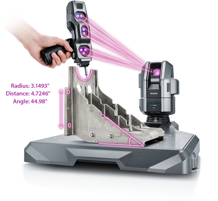
Source: KEYENCE Website(https://www.keyence.com/products/measure-sys/cmm/xm/index_pr.jsp)
This CMM has a caliper-like feel, enabling even beginners to perform high-precision measurements. It can be carried without the need for temperature control, allowing for immediate measurements at any desired location and time. As it doesn't require a large installation space, it's a CMM with a low entry barrier.
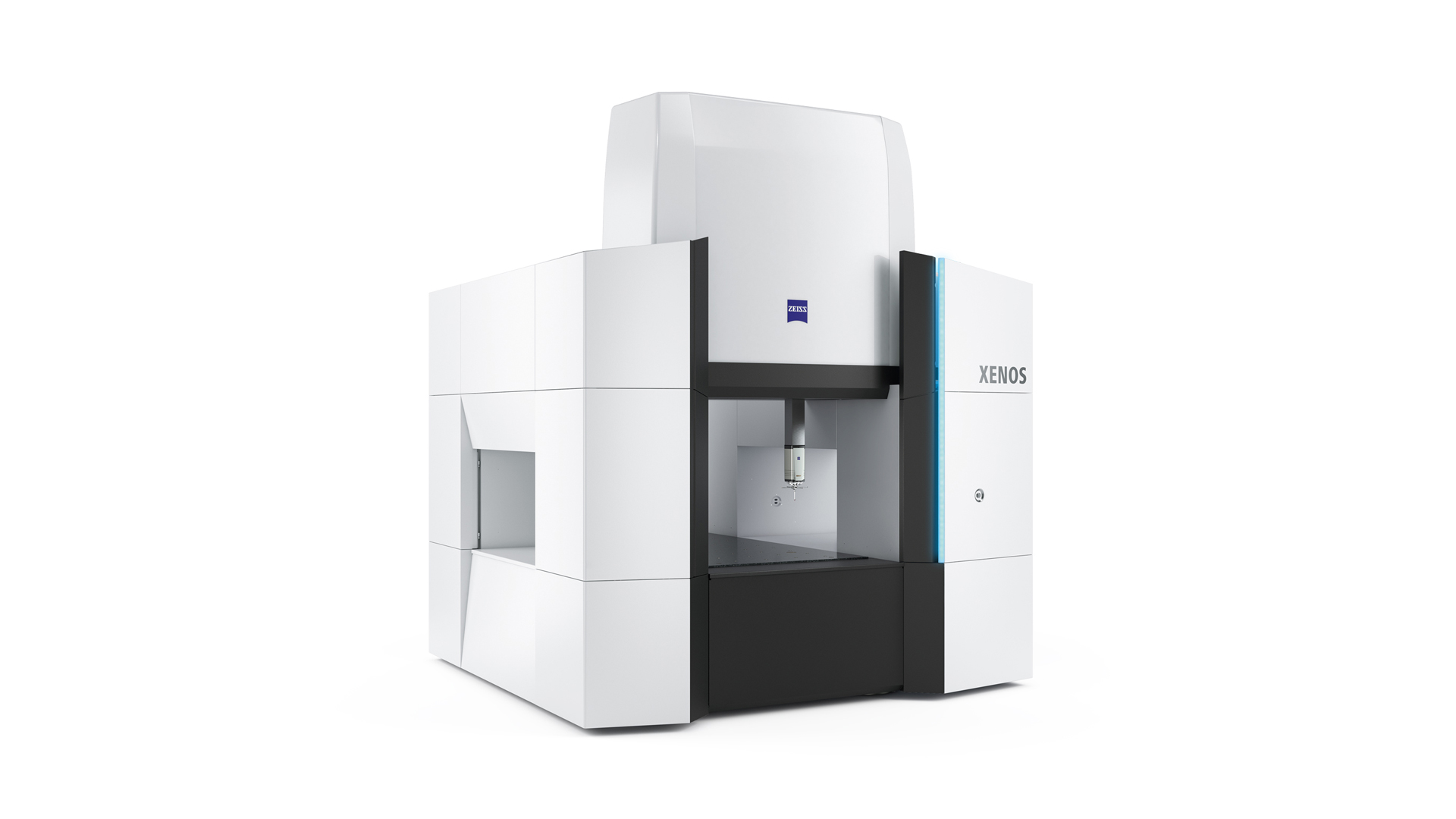
Source: Carl Zeiss Website(https://www.zeiss.com/metrology/products/systems/cmm.html)
Utilizing linear drive on all axes, this CMM boasts high precision with a maximum permissible length measurement error of 0.3+L/1000μm, repeatability of ±0.2μm, and resolution of 0.001μm. The reduced occurrence of errors allows for a decrease in the need for remeasurement.
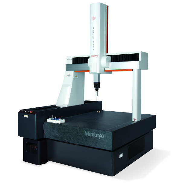
Source: Mitutoyo Website(https://www.mitutoyo.com/products/coordinate-measuring-machines/)
A CNC CMM that was first developed in 1976.
It features applications that respond to the demand for "Smart Factories" by allowing monitoring of operational status and maintenance management of the machine through the network.
Reasons for Selection