![]()
![]()


In modern manufacturing, product quality is defined not only by dimensional accuracy but also by how precisely a part follows its intended shape. As product designs become more complex, traditional dimensional tolerances alone are often insufficient to fully control form and functionality. One of the most important geometric tolerances for evaluating complex shapes is profile tolerance.
The measurement of profile tolerance with a CMM (Coordinate Measuring Machine) allows manufacturers to evaluate whether actual part geometry conforms to the nominal design within a specified tolerance zone. Profile tolerance is widely used in industries such as automotive, aerospace, medical devices, and precision machining, where even small deviations from the intended profile can affect performance, assembly, or durability.
This article provides a detailed overview of profile tolerance, focusing on line profiles, surface profiles, and practical methods for measuring them accurately using a CMM.
Profile tolerance for a line controls how much a measured line may deviate from its ideal, theoretically exact profile. Unlike size tolerances that only limit dimensions such as length or diameter, profile tolerance evaluates the overall shape accuracy of a feature.
The tolerance zone for a line profile is defined by two parallel curves that are offset from the nominal profile by an equal amount in both directions. All measured points along the actual line must lie entirely within this zone.
Because of these characteristics, profile tolerance for lines is commonly applied to grooves, cam profiles, sealing surfaces, aerodynamic contours, and molded or machined shapes where smoothness and continuity are critical.
In addition to line profiles, profile tolerance can also be applied to entire surfaces. A surface profile tolerance controls the three-dimensional shape of a feature by defining a tolerance zone bounded by two offset surfaces that follow the nominal CAD geometry.
Surface profile tolerance is particularly effective for complex freeform surfaces, such as sculpted exterior panels, turbine blades, die-cast components, and plastic parts. It allows designers to control the overall form without over-constraining individual dimensions.
When measuring surface profiles, it is essential to consider sampling density, scanning paths, and alignment strategy. Insufficient measurement data may fail to capture local deviations, while excessive data may increase inspection time without added value.
A CMM is one of the most reliable tools for measuring profile tolerance due to its high accuracy, repeatability, and flexibility. Modern CMMs support both discrete point probing and continuous scanning, making them suitable for a wide range of profile measurements.
Many CMM systems provide color deviation maps and statistical outputs, enabling engineers to visually identify problem areas and improve manufacturing processes.
To obtain reliable and repeatable results when measuring profile tolerance with a CMM, several best practices should be followed:
Applying these practices helps reduce measurement variation and ensures that inspection results accurately reflect the true condition of the part.
Measuring profile tolerance with a CMM provides manufacturers with a powerful method for verifying complex shapes and ensuring design intent is met. By combining precise hardware with advanced software and well-defined measurement strategies, CMMs enable consistent and objective evaluation of both line and surface profiles.
As product designs continue to evolve toward greater complexity, the role of profile tolerance and CMM-based inspection will become increasingly important. Proper implementation not only improves product quality but also supports process optimization, cost reduction, and long-term manufacturing stability.
Source: KEYENCE Website(https://www.keyence.com/products/measure-sys/cmm/xm/index_pr.jsp)
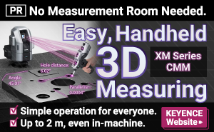
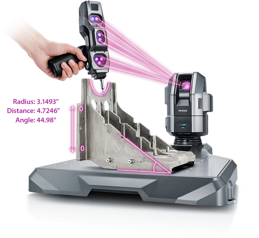
This CMM has a caliper-like feel, enabling even beginners to perform high-precision measurements. It can be carried without the need for temperature control, allowing for immediate measurements at any desired location and time. As it doesn't require a large installation space, it's a CMM with a low entry barrier.
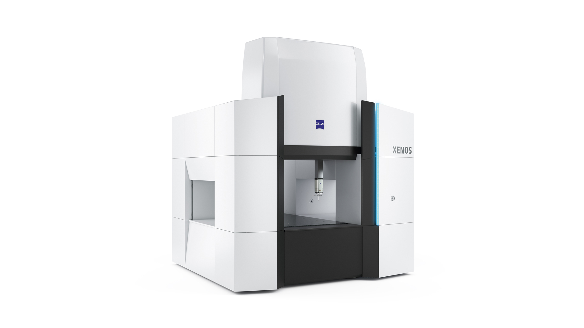
Source: Carl Zeiss Website(https://www.zeiss.com/metrology/products/systems/cmm.html)
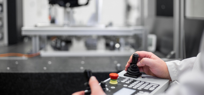
Utilizing linear drive on all axes, this CMM boasts high precision with a maximum permissible length measurement error of 0.3+L/1000μm, repeatability of ±0.2μm, and resolution of 0.001μm. The reduced occurrence of errors allows for a decrease in the need for remeasurement.
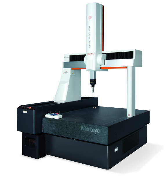
Source: Mitutoyo Website(https://www.mitutoyo.com/products/coordinate-measuring-machines/)
A CNC CMM that was first developed in 1976.
It features applications that respond to the demand for "Smart Factories" by allowing monitoring of operational status and maintenance management of the machine through the network.
Reasons for Selection