![]()
![]()


As product designs become increasingly complex and functional requirements more demanding, geometric tolerances play a critical role in ensuring consistent quality and performance. Among these tolerances, symmetry tolerance is often misunderstood or overlooked, despite its importance in controlling balanced geometry and functional alignment.
Symmetry tolerance is particularly relevant for components where equal distribution around a center plane or axis is required, such as shafts, slots, housings, and structural parts. When symmetry is not properly controlled, even small deviations can lead to uneven load distribution, vibration, assembly difficulties, or aesthetic defects.
Coordinate Measuring Machines (CMMs) provide an effective and reliable means of evaluating symmetry tolerance. By combining precise probing, datum-based alignment, and advanced software analysis, CMMs enable manufacturers to verify symmetry in accordance with geometric dimensioning and tolerancing (GD&T) standards. This article explains what symmetry tolerance is, how it is defined, and how it can be measured accurately using a CMM in practical manufacturing environments.
Symmetry tolerance is a geometric tolerance that controls how symmetrically a feature or set of features is distributed about a specified datum plane or datum axis. It defines the allowable variation of a feature’s median points relative to the theoretical center plane or axis established by the datum.
In GD&T, symmetry tolerance is used to ensure that opposing or repeated features are equally positioned with respect to a reference. Unlike dimensional tolerances, which control size or distance, symmetry tolerance focuses on geometric balance rather than absolute dimensions.
One defining aspect of symmetry tolerance is that it applies to the median points of a feature. For example, when evaluating a slot, symmetry tolerance controls how evenly the slot’s center plane aligns with the datum plane, not the individual surfaces themselves.
Symmetry tolerance is always specified in relation to a datum. Without a datum reference, symmetry cannot be defined or evaluated. The tolerance zone is typically represented as two parallel planes (for planar symmetry) or a cylindrical zone (for axial symmetry), centered on the datum.
Because symmetry tolerance controls balance rather than size, it is especially important for components where functional performance depends on even geometry. Examples include rotating parts, mating features, and structural components that must distribute loads evenly.
Coordinate Measuring Machines are well suited for symmetry measurement because they can capture multiple points across complex geometries and calculate median features with high precision. Unlike simple gauges, a CMM can evaluate symmetry in three dimensions while maintaining a clear relationship to the datum system.
The general approach to measuring symmetry tolerance with a CMM involves establishing a datum reference, measuring the relevant features, and calculating how far the feature’s median points deviate from the ideal symmetric position.
The first step in symmetry measurement is defining the datum specified on the drawing. This may be a plane, an axis, or a combination of features. The datum establishes the theoretical center plane or axis against which symmetry is evaluated.
Using the CMM software, the datum feature is measured and aligned to create a stable coordinate system. Accurate datum definition is critical, as any error at this stage directly affects the symmetry evaluation.
Once the datum is established, the feature subject to symmetry tolerance is measured. This may involve probing multiple points on opposing surfaces, edges, or profiles, depending on the feature type.
For example, when measuring a slot, the CMM probes both side surfaces to determine their geometry. The software then calculates the median plane between these surfaces, which represents the functional center of the feature.
After the median feature is determined, the CMM software evaluates how far this median plane or axis deviates from the ideal position defined by the datum. The maximum deviation is compared to the specified symmetry tolerance value.
If all calculated median points fall within the tolerance zone centered on the datum, the feature meets the symmetry requirement. If not, the part is considered nonconforming.
While the measurement process itself may appear straightforward, several practical factors influence the accuracy and reliability of symmetry evaluation.
The number and distribution of probing points significantly affect the calculated median feature. Insufficient or poorly distributed points may not represent the true geometry, leading to inaccurate symmetry results.
Probe selection, including stylus length, tip diameter, and orientation, also plays an important role. Excessive stylus deflection or inappropriate probing angles can introduce errors that distort symmetry calculations.
In addition, different CMM software packages may apply different algorithms when calculating median features and tolerance zones. Understanding how the software interprets symmetry ensures consistent evaluation and reliable comparison of results.
Symmetry tolerance plays a vital role in controlling balanced geometry and ensuring consistent functional performance. Although it is less commonly applied than other geometric tolerances, its importance becomes evident in applications where alignment, load distribution, or visual balance is critical.
By using a Coordinate Measuring Machine, manufacturers can measure symmetry tolerance accurately and repeatably. Proper datum definition, thoughtful measurement planning, and careful interpretation of results allow symmetry requirements to be verified with confidence.
As product designs continue to evolve and tolerance requirements become more sophisticated, understanding how to measure symmetry tolerance with a CMM helps ensure that geometric intent is accurately translated into reliable, high-quality parts.
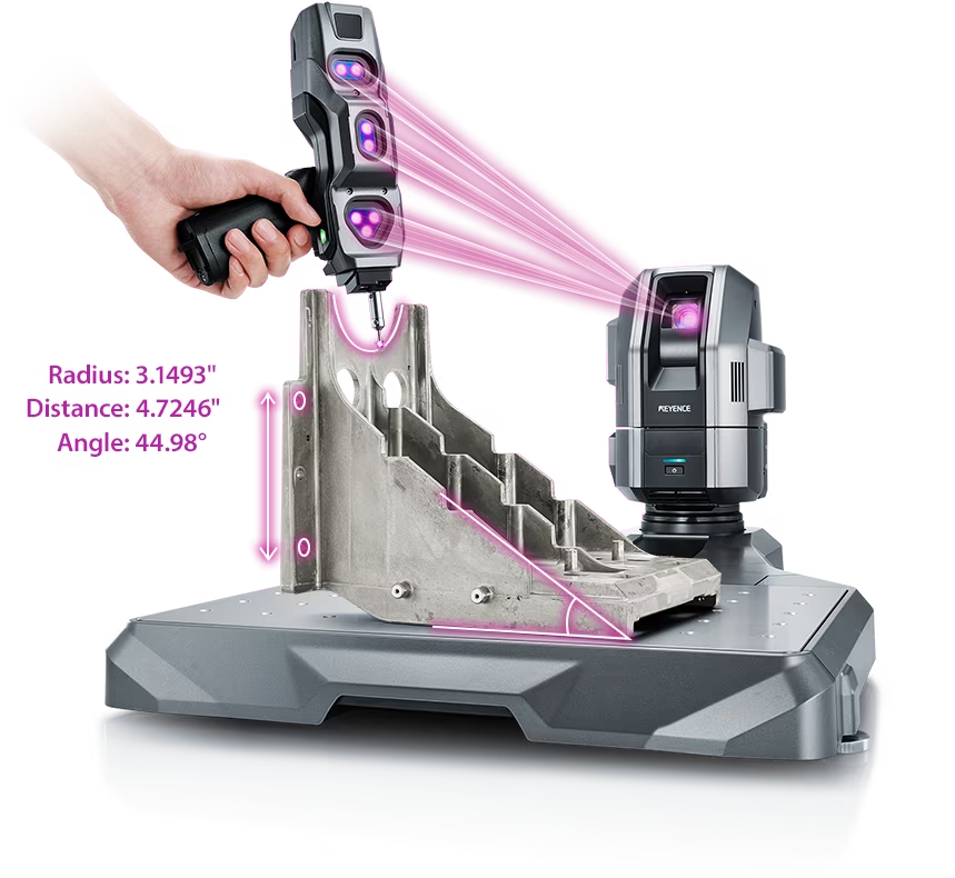
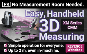
Source: KEYENCE Website(https://www.keyence.com/products/measure-sys/cmm/xm/index_pr.jsp)
This CMM has a caliper-like feel, enabling even beginners to perform high-precision measurements. It can be carried without the need for temperature control, allowing for immediate measurements at any desired location and time. As it doesn't require a large installation space, it's a CMM with a low entry barrier.
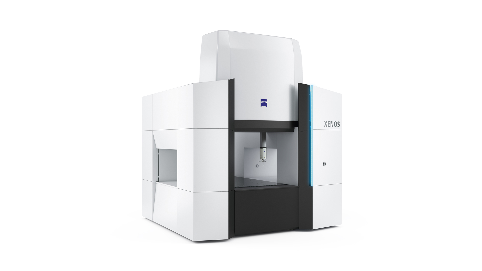
Source: Carl Zeiss Website(https://www.zeiss.com/metrology/products/systems/cmm.html)
Utilizing linear drive on all axes, this CMM boasts high precision with a maximum permissible length measurement error of 0.3+L/1000μm, repeatability of ±0.2μm, and resolution of 0.001μm. The reduced occurrence of errors allows for a decrease in the need for remeasurement.
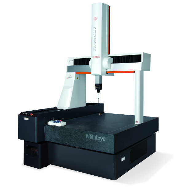
Source: Mitutoyo Website(https://www.mitutoyo.com/products/coordinate-measuring-machines/)
A CNC CMM that was first developed in 1976.
It features applications that respond to the demand for "Smart Factories" by allowing monitoring of operational status and maintenance management of the machine through the network.
Reasons for Selection