Introduction
In precision manufacturing, maintaining correct geometric relationships between features is just as important as achieving accurate dimensions. Even when individual dimensions are within tolerance, a product may fail to function as intended if critical features are not properly oriented. One of the most fundamental geometric relationships is perpendicularity.
When surfaces or axes are not correctly perpendicular, problems such as assembly interference, uneven contact, vibration, or premature wear can occur. These issues are especially critical in industries such as automotive, aerospace, medical devices, and precision machinery, where tight tolerances and reliable performance are required.
The measurement of perpendicularity with a CMM (Coordinate Measuring Machine) provides a reliable and objective method for verifying right-angle relationships with high accuracy. By using defined datums and mathematically constructed tolerance zones, CMMs allow manufacturers to confirm that parts meet both design intent and functional requirements.
This article explains what perpendicularity tolerance is, why it is important, and how it can be effectively measured using a CMM in real manufacturing environments.
What Is Perpendicularity?
Perpendicularity is a type of orientation tolerance that controls how much a feature may deviate from a perfect 90-degree relationship relative to a reference datum. It does not control the size or position of a feature, but rather its angular relationship to another feature.
Unlike angular tolerances expressed in degrees or minutes, perpendicularity is defined using a tolerance zone. This zone limits the allowable variation of a surface or axis while maintaining its orientation relative to the specified datum.
- Perpendicularity always references a datum feature.
- It controls orientation only, not size or location.
- It can be applied to surfaces, centerlines, or axes.
- The tolerance zone is defined geometrically rather than by angle.
For a surface, perpendicularity is controlled by two parallel planes that are perpendicular to the datum plane. The entire measured surface must lie within this zone. For an axis, the tolerance zone is a cylinder that is oriented perpendicular to the datum. The derived axis of the feature must remain within this cylindrical zone.
Perpendicularity tolerance is widely used for mounting faces, mating surfaces, holes, shafts, and machined features where accurate alignment is essential for assembly and performance.
Importance of Perpendicularity in Manufacturing
Correct perpendicularity plays a critical role in ensuring that components fit together and function as designed. Even small angular deviations can be amplified across assemblies, leading to cumulative errors and reduced product quality.
Typical problems caused by insufficient perpendicularity include difficulty during assembly, uneven load distribution, increased friction, noise, vibration, and reduced service life. In sealing or bearing applications, poor perpendicularity can also result in leakage or premature failure.
By specifying perpendicularity tolerance instead of overly tight dimensional limits, designers can clearly communicate functional requirements while allowing reasonable manufacturing variation. This helps achieve an optimal balance between quality, cost, and productivity.
Measuring Perpendicularity with a Coordinate Measuring Machine
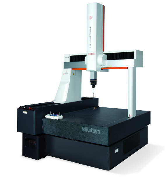
A coordinate measuring machine is one of the most effective tools for evaluating perpendicularity because it can accurately establish datums, collect precise three-dimensional measurement data, and mathematically evaluate orientation. Modern CMM systems combine high-precision hardware with advanced software, enabling consistent and repeatable inspection results.
1. Datum Establishment
The first step in perpendicularity measurement is defining the datum feature specified on the engineering drawing. The datum may be a plane, an axis, or another feature that serves as the reference for orientation.
The CMM measures the datum by collecting multiple points and constructing an ideal reference plane or axis using best-fit algorithms. This datum defines the orientation of the perpendicularity tolerance zone. Any error in datum establishment will directly influence the measurement result, making this step especially important.
2. Measurement of the Target Feature
After establishing the datum, the feature being evaluated for perpendicularity is measured. For surfaces, multiple points or scanning paths are used to capture the actual form of the feature. For holes or shafts, the CMM calculates the derived axis based on the measured data.
Adequate point distribution is essential. Measuring too few points may fail to capture form errors, while excessive data may increase inspection time without improving accuracy.
3. Construction of the Tolerance Zone
Once the datum and target feature are defined, the CMM software constructs the perpendicularity tolerance zone according to the specified tolerance value. For surface perpendicularity, this consists of two parallel planes oriented at 90 degrees to the datum. For axis perpendicularity, the tolerance zone is a cylinder perpendicular to the datum.
The software then evaluates whether the measured feature lies entirely within this zone. Deviations are calculated as the minimum distance required to bring the feature into perfect perpendicular alignment.
4. Evaluation and Reporting
Measurement results are presented numerically and graphically. Many CMM systems provide color maps, deviation vectors, and statistical summaries that make it easy to identify orientation errors and trends.
These results can be used not only for pass/fail inspection but also for process optimization, root cause analysis, and continuous improvement.
Best Practices for Accurate Perpendicularity Measurement
To achieve reliable and repeatable perpendicularity measurements with a CMM, several best practices should be followed:
- Secure the workpiece using stable and appropriate fixturing to prevent movement.
- Select probe types, stylus lengths, and probing angles that minimize measurement uncertainty.
- Use scanning measurement for flat or critical orientation features whenever possible.
- Follow drawing specifications exactly when defining datums and tolerance references.
- Ensure the CMM is properly calibrated and regularly maintained.
Applying these practices helps reduce measurement variation and ensures that inspection results accurately reflect the true orientation of the part.
Measure Perpendicularity Accurately with a CMM
The measurement of perpendicularity with a CMM is an essential element of modern geometric inspection. By combining precise measurement hardware, robust software algorithms, and well-defined inspection strategies, manufacturers can verify right-angle relationships with a high degree of confidence.
As product designs continue to evolve toward greater complexity and tighter tolerances, accurate perpendicularity measurement will play an increasingly important role in quality assurance. Implementing proper CMM-based inspection not only improves product quality but also supports efficient manufacturing processes and long-term reliability.