
Introduction
In modern manufacturing, dimensional accuracy alone is no longer sufficient to ensure proper function and assembly. Even when individual features meet size requirements, incorrect feature location can lead to assembly difficulties, increased wear, or functional failure. For this reason, true position tolerance plays a critical role in geometric dimensioning and tolerancing (GD&T).
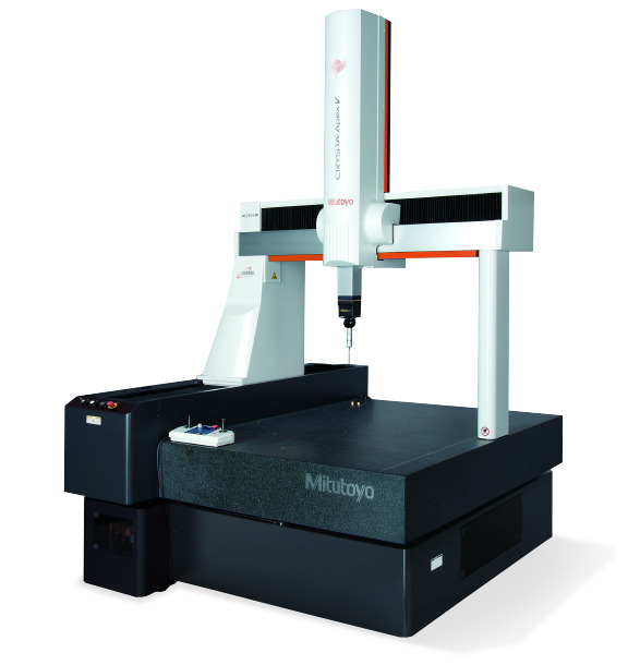
Coordinate Measuring Machines (CMMs) are widely used to evaluate true position because they can establish precise datum reference frames and calculate three-dimensional feature locations with high accuracy. However, accurate true position measurement requires careful attention to datum definition, probing strategy, and tolerance interpretation.
This article explains what true position tolerance is and how it is measured using a CMM, focusing on practical considerations that support reliable and repeatable inspection results.
What Is True Position Tolerance?
True position tolerance controls how far the actual location of a feature may deviate from its theoretically exact position. Rather than controlling size or form, it defines the allowable variation in the spatial relationship between features and specified datums.
True position is commonly applied to functional features such as holes, pins, and slots that must align accurately with mating components. In GD&T, it is typically represented by the position symbol along with a tolerance value, often accompanied by a diameter symbol indicating a cylindrical tolerance zone.
Compared with traditional coordinate tolerancing, true position tolerance offers several advantages. It defines a clear tolerance zone, reflects functional requirements more accurately, and often allows greater manufacturing freedom while maintaining performance.
Measuring True Position with a CMM
A CMM is particularly well suited for true position measurement because it can establish datums, capture feature geometry in three dimensions, and perform mathematical evaluations automatically. However, the quality of the result depends heavily on how the measurement process is executed.
STEP 1: Define Datums Using the CMM
The first step in true position measurement is establishing the datum reference frame. Datums define the coordinate system used to evaluate feature location and orientation.
Primary datums are often defined using planar surfaces, while secondary and tertiary datums may be defined by perpendicular planes or cylindrical features. The order in which datums are established is critical, as it determines how the part is oriented within the CMM coordinate system.
Incorrect datum selection or probing strategy can significantly affect measured true position values. Even small datum misalignments can lead to large differences in pass/fail judgments.
STEP 2: Probe the Target Feature with the Stylus
After defining the datum reference frame, the target feature is measured by probing it with the stylus. The probing strategy depends on the feature geometry and inspection requirements.
For holes or cylindrical features, multiple probing points are typically collected around the circumference and at different heights to calculate the feature axis accurately. For slots or other shapes, probing along relevant surfaces may be required.
The number and distribution of probing points affect the stability of the calculated feature center or axis. Too few points can lead to unstable results, while excessive probing may increase inspection time without improving accuracy.
STEP 3: Specify the Presence or Absence of the Diameter Symbol
In true position evaluation, it is essential to confirm whether the tolerance zone is defined with a diameter symbol. When the diameter symbol is specified, the tolerance zone is cylindrical, and the feature axis or center must lie within that cylindrical region.
If no diameter symbol is specified, the tolerance zone may be defined differently depending on drawing standards and feature type. CMM software relies on this information to calculate positional deviation correctly.
Misinterpreting the tolerance zone definition is a common source of inspection errors, even when the measurement itself is performed correctly.
When the Measured Feature Is Not Parallel
In practice, features are not always perfectly parallel to their datum references. When a feature is tilted or misaligned, the method used to calculate true position becomes especially important.
CMMs typically determine true position by calculating the actual axis or center of the feature and comparing it to the theoretically exact position within the datum reference frame. If orientation errors are not controlled separately, they can influence positional results.
In such cases, combining true position tolerance with orientation tolerances such as perpendicularity or parallelism may be necessary to achieve the intended functional control.
Practical Considerations for Measuring True Position with a CMM
Measuring true position with a CMM requires more than simply following software instructions. Reliable results depend on consistent datum definition, appropriate probing strategies, and correct interpretation of tolerance zones.
Datums should always be established according to the functional intent of the drawing, not merely for convenience. The datum reference frame defines how the part is evaluated and directly influences true position results.
Probing strategies should be designed to balance accuracy and efficiency. Selecting appropriate stylus configurations, minimizing stylus deflection, and distributing probing points evenly around the feature all contribute to stable measurements.
Finally, inspectors should verify how the tolerance zone is interpreted in the CMM software, especially when diameter symbols or complex datum structures are involved. Understanding the principles behind true position evaluation helps prevent misjudgment and supports consistent inspection decisions.
When applied correctly, true position measurement with a CMM provides clear and functional insight into part quality. It supports reliable assembly, reduces ambiguity in inspection results, and contributes to effective geometric control in precision manufacturing.