![]()
![]()


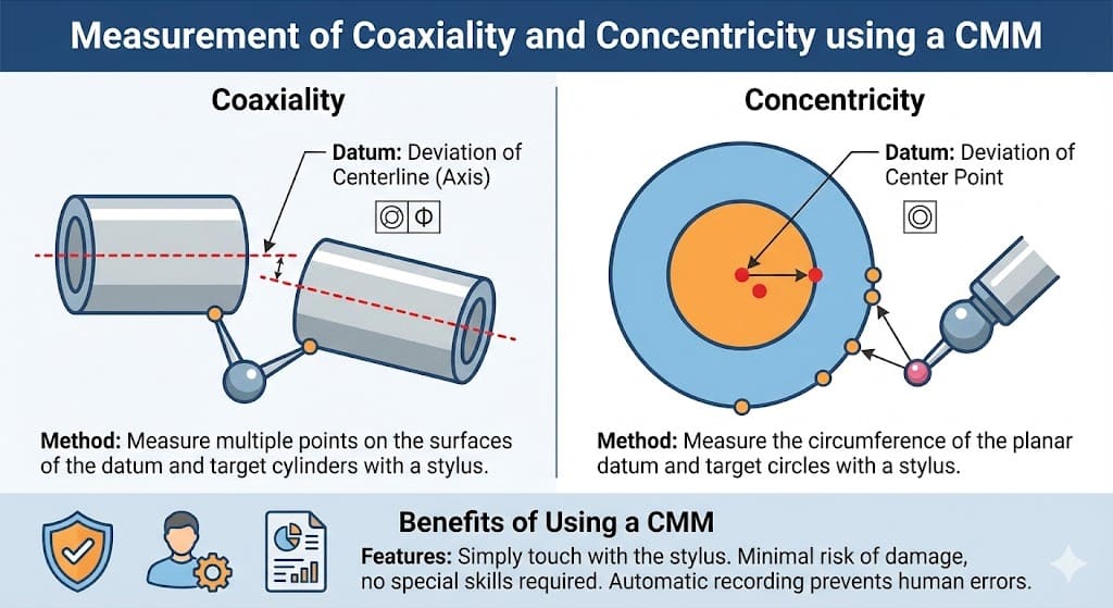
By using a 3D coordinate measuring machine, it is possible to measure by specifying the coordinates in the three-dimensional space (X, Y, Z). In this article, we will explain how to measure concentricity and coaxiality using a 3D coordinate measuring machine.
"Coaxiality", a term used in machining, refers to the alignment of the axes of two cylinders such that their central axes are not displaced. The degree of displacement is indicated by the coaxiality value. This is a geometric tolerance that specifies how much deviation is allowed between the datum axis and the indicated axis. Tolerances are denoted with the symbol "Φ".
For example, if the deviation from the datum axis is required to be within 0.1mm, it would be specified as "◎Φ0.1".
The symbol "◎" is the JIS symbol for coaxiality.
"Concentricity" refers to the condition where the axes of two cylinders are aligned and there is no displacement at the central point. The degree of eccentricity or deviation from the center point is expressed by the concentricity value.
While the reference for coaxiality is the centerline, the reference for concentricity is the center point, which is a significant difference. Like coaxiality, concentricity is represented by the JIS symbol "◎" (double circle).
Measuring coaxiality is very straightforward. First, to measure coaxiality, place the stylus on the measurement points of the cylindrical reference element. The stylus is the part that comes into contact with the object being measured and can be spherical or needle-shaped.
Next, place the stylus on the measurement points of the target cylinder, and the coaxiality measurement can be performed. It can be difficult to reach the inside of the cylinder with the stylus, but using point measurements and the auto-trigger function will help. The results are recorded by the measuring machine, and if the machine can output reports directly, there is no risk of input errors, saving time and reducing the risk of mistakes.
To measure concentricity with a 3D coordinate measuring machine, measurements are made on flat circles. Place the stylus on the measurement points of the reference circle. Then, place the stylus on the measurement points of the target circle and continue the measurement.
While it may be necessary to apply a strong force during measurement, this can damage the object. However, with a 3D coordinate measuring machine, there is no need to apply excessive force to the stylus, allowing for accurate measurements without damaging the object.
Using a 3D coordinate measuring machine, you can measure the coaxiality and concentricity explained in this article. Other measurement methods, such as using a dial gauge, are also available. However, these methods carry the risk of damaging the object during measurement and require a certain level of skill.
With a 3D coordinate measuring machine, measurements can be made without special skills, so consider using it for your measurements.
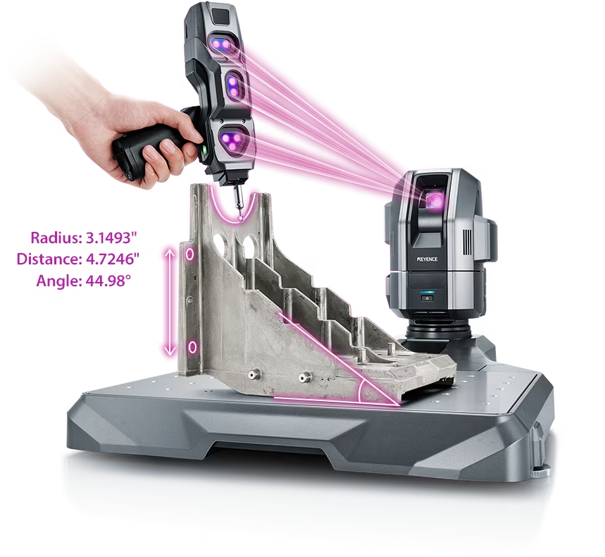
Source: KEYENCE Website(https://www.keyence.com/products/measure-sys/cmm/xm/index_pr.jsp)
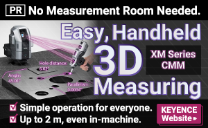
This CMM has a caliper-like feel, enabling even beginners to perform high-precision measurements. It can be carried without the need for temperature control, allowing for immediate measurements at any desired location and time. As it doesn't require a large installation space, it's a CMM with a low entry barrier.
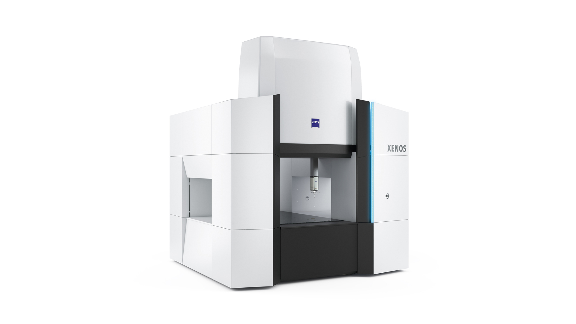
Source: Carl Zeiss Website(https://www.zeiss.com/metrology/products/systems/cmm.html)
Utilizing linear drive on all axes, this CMM boasts high precision with a maximum permissible length measurement error of 0.3+L/1000μm, repeatability of ±0.2μm, and resolution of 0.001μm. The reduced occurrence of errors allows for a decrease in the need for remeasurement.
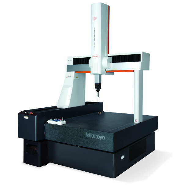
Source: Mitutoyo Website(https://www.mitutoyo.com/products/coordinate-measuring-machines/)
A CNC CMM that was first developed in 1976.
It features applications that respond to the demand for "Smart Factories" by allowing monitoring of operational status and maintenance management of the machine through the network.
Reasons for Selection