![]()
![]()


Parallelism is one of the most commonly specified geometric tolerances in mechanical design, particularly for components that require smooth motion, uniform load distribution, or consistent assembly alignment. Even small deviations in parallelism can cause functional issues such as uneven wear, vibration, noise, or difficulties during assembly. For manufacturers working in precision-driven environments, evaluating parallelism accurately is therefore a critical inspection task.
A Coordinate Measuring Machine (CMM) provides a reliable and repeatable method for measuring parallelism tolerance. By combining precise probing, stable datum definition, and advanced software evaluation, CMMs allow manufacturers to verify whether functional surfaces and features meet design intent. This article explains the concept of parallelism, clarifies how it differs from flatness, and outlines a practical approach to measuring parallelism using a CMM.
Parallelism is a geometric tolerance that controls the orientation of a feature relative to a specified datum. It defines how closely a surface, line, or axis must remain parallel to a reference feature. Unlike size tolerances, which limit dimensions, parallelism focuses solely on orientation and spatial relationship.
In GD&T, a parallelism tolerance creates a tolerance zone consisting of two parallel planes for a surface, or two parallel lines for a line or axis. The measured feature must lie entirely within this zone when oriented relative to the datum. The width of the tolerance zone represents the allowable variation.
Parallelism is commonly applied to sliding surfaces, opposing faces that must support uniform clamping or loading, and shafts or holes that need to maintain consistent orientation during assembly or operation. By specifying parallelism, designers can control functional relationships without unnecessarily restricting the overall geometry of the part.
Parallelism and flatness are often confused because both relate to surface geometry, but they control fundamentally different characteristics.
Flatness controls the form of a surface itself. A flatness tolerance defines a zone bounded by two parallel planes within which the entire surface must lie. Importantly, flatness does not reference any datum; it evaluates how flat a surface is, independent of its orientation or position in space.
Parallelism, by contrast, always references a datum. Even if a surface is perfectly flat, it can still fail a parallelism requirement if it is tilted relative to the datum. Conversely, a surface may satisfy a parallelism tolerance while still exhibiting some form error, as long as the entire surface remains within the specified parallel tolerance zone relative to the datum.
In simple terms, flatness answers the question “How flat is this surface?”, while parallelism answers “How parallel is this surface to the datum?”. Understanding this distinction is essential when selecting appropriate tolerances and inspection methods.
A CMM measures parallelism by first establishing a stable datum reference and then evaluating the orientation of the target feature relative to that datum. This process relies on both an appropriate probing strategy and correct software evaluation.
Modern CMM software calculates parallelism by constructing ideal geometric elements from measured points and comparing their orientation to the datum. This minimizes operator influence and improves repeatability compared to manual inspection techniques.
The first step is to identify and measure the feature whose parallelism is being evaluated. Depending on the drawing specification, this may be a plane, a line, or an axis.
Using the CMM probe, multiple points are collected across the surface or along the feature. For planar features, points should be distributed evenly across the functional area to capture overall orientation rather than local surface irregularities. For linear features or axes, sufficient probing along the length is required to define a reliable reference.
Based on these measurements, the CMM software constructs an ideal geometric element such as a best-fit plane or line.
Parallelism is always evaluated relative to a datum, making datum definition a critical step. The datum may be a plane, line, or axis, depending on the functional requirement shown on the drawing.
The datum feature must be measured first and established within the CMM’s coordinate system. This ensures the part is correctly aligned before evaluating the target feature. Inadequate probing or unstable datum definition can result in inconsistent or misleading measurement results.
Once defined, the datum is fixed as the reference against which parallelism is calculated.
To accurately assess parallelism, the stylus should contact the target feature at multiple locations. In many practical inspections, four or more points are used as a minimum, though larger or more complex surfaces may require additional points.
Probing multiple locations helps reduce the influence of localized defects, capture overall orientation trends, and improve repeatability. The CMM software evaluates the orientation of the constructed feature relative to the datum and calculates the minimum distance between two parallel planes or lines that fully enclose the feature.
This calculated value is then compared with the specified tolerance to determine whether the feature meets the parallelism requirement.
Measuring parallelism with a CMM provides a high level of accuracy, repeatability, and efficiency compared with traditional manual inspection methods. By clearly understanding the definition of parallelism, distinguishing it from flatness, and following a structured measurement workflow, manufacturers can evaluate orientation tolerances with confidence.
As geometric tolerances become tighter and functional requirements more demanding, CMM-based parallelism measurement remains an essential technique for ensuring consistent product quality, reliable assembly, and stable long-term performance.
Source: KEYENCE Website(https://www.keyence.com/products/measure-sys/cmm/xm/index_pr.jsp)
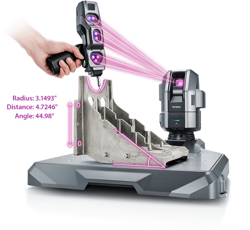
This CMM has a caliper-like feel, enabling even beginners to perform high-precision measurements. It can be carried without the need for temperature control, allowing for immediate measurements at any desired location and time. As it doesn't require a large installation space, it's a CMM with a low entry barrier.
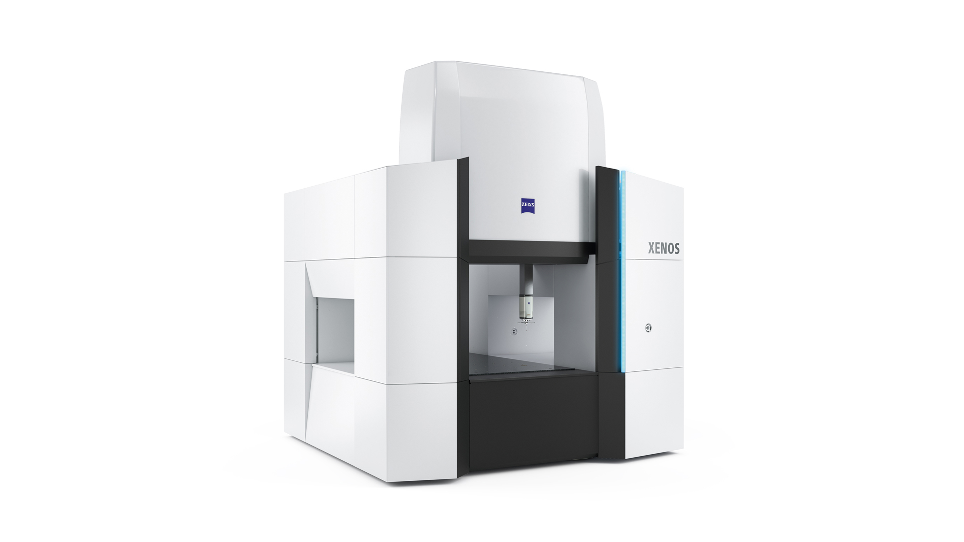
Source: Carl Zeiss Website(https://www.zeiss.com/metrology/products/systems/cmm.html)
Utilizing linear drive on all axes, this CMM boasts high precision with a maximum permissible length measurement error of 0.3+L/1000μm, repeatability of ±0.2μm, and resolution of 0.001μm. The reduced occurrence of errors allows for a decrease in the need for remeasurement.
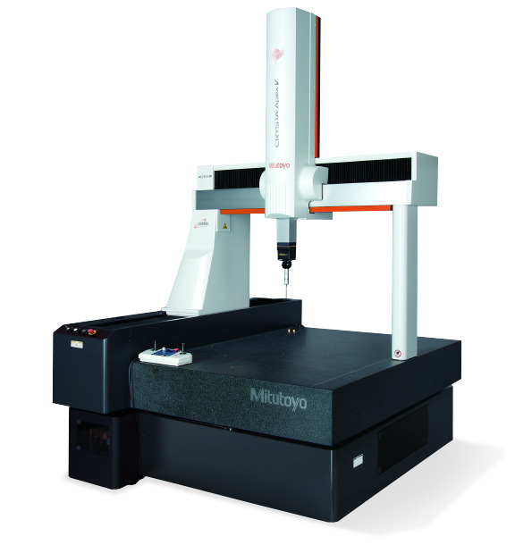
Source: Mitutoyo Website(https://www.mitutoyo.com/products/coordinate-measuring-machines/)
A CNC CMM that was first developed in 1976.
It features applications that respond to the demand for "Smart Factories" by allowing monitoring of operational status and maintenance management of the machine through the network.
Reasons for Selection